GE-200-SV Laser Scanner motion Controller Series
.
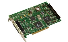
GE-200-SV-LASER
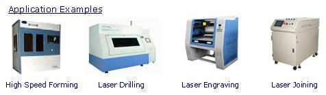
This motion controllers is specially designed for laser applications and it is based on the structure of higher frequency DSP processor and FPGA technology. This GE-200-SV type of controller can control scanner, motors and laser synchronously and effectively. The scanning capability varies from small scan field to large scan field, suitable for the uses of laser cutting, laser engraving, laser drilling, etc.
Technical Specification
Motor Motion Control:
2 Axes of linear or circular interpolation.
Motion pause, stop and resume.
List (buffer) commands and immedicate commands.
Automatically stop the motion when the LIMIT is triggered.
200us motor control cycle
HOME and INDEX signal hardware capture, high speed position locked.
Pulse output frequency: linear interpolation up to 256KHz, circular interpolation up to 160KHz.
Command enable or disable the LIMIT and ALARM input.
8K buffer for storing motion information.
Support the management of coordinate system offset.
Two channels of pulse or voltage output. Output mode switchable.
Supply the delay between two motion commands, in pulse out mode, the unit is: 200us, in voltage out mode, the unit is: 10us.
Scanner Control:
Analogy voltage output for scanner control only, offering 2 axes linear or circular interpolation.
Two modes of the marking on the fly: with or without encoder feedback.
Two types of interfaces are provided for the controller and the scanner driver: analog voltage interface and series data transfer interface (XY2-100).
Laser Control:
One channel of HSIO to control laser power On/Off.
Laser power On/Off delay, the delay unit: 1us.
Three types of laser power signal control: PWM and Pulse frequency.