|
|

SYSTAT : SIGMAPLOT : TableCurve2D : TableCurve3D : PeakFIT : AutoSignal |
PRODUCT USES |
|---|
MEAT MARBLING
This application shows how SigmaScan Pro may be used to determine the area percentage and spatial distribution of fat in a cut of meat (1). Fat areas and x,y center of gravity positions are measured and an interesting application of overlay layer mathematics is shown.
A pork chop was imaged using a commercially available frame grabber and a black and white solid-state CCD camera (Figure 1).
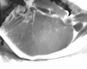
Figure 1: Original pork chop image
A two-point calibration is used across the 5 inch width of the pork chop (Image, Calibrate, Distance and Area) to obtain measurements in inches units. The outline of the meat section is necessary since a quantitative measurement of the percentage of fat is required.
Set up the options in Measurements, Settings… to outline the pork chop and make subsequent measurements of fat center of mass positions and area. Select CM Binary X, CM Binary Y and Area in the Measurements tab to be placed in columns A, B and C of the worksheet. Select Continuous Streaming in the Trace tab. From the Overlays tab select the Source Overlay to be yellow.
To trace the meat outline select Trace Measurement Mode from the Mode menu (or click the Trace Mode icon in the Measurement Toolbar). Press the left mouse button and trace the meat outline. When you have nearly completed the tracing, right click to connect the last point to the first. The outline will be filled and the area computed. This is shown with a yellow overlay in Figure 2.
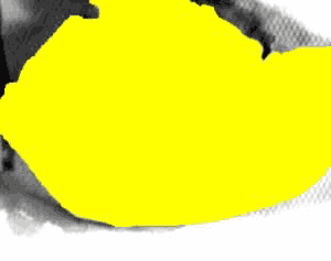
Figure 2: Traced outline and yellow overlay fill
Uncheck the yellow overlay from the View menu to display the original image. An Intensity Threshold of the original image is now performed over the range [190-255] to show the fatty area (Select Image, Threshold, Intensity Threshold). This is shown as the red overlay plane in Figure 3.
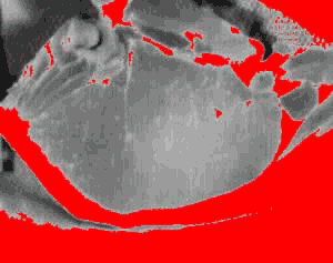
Figure 3: Identification of fatty areas using an intensity threshold
Overexposed areas outside the meat can be excluded by intersecting the yellow and red overlay planes. Use the Overlay Math feature in the Image menu to do this. Select Source 1 and Source 2 to be the red and yellow overlay planes and the Destination overlay plane to be blue. Selecting the And operation intersects these two overlay planes and produces the fat objects shown in Figure 4.
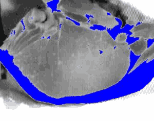
Figure 4: Fat regions produced by excluding areas outside the meat section
Select Measurements, Measure Objects to measure all fat objects. The x,y locations of the centers of mass and areas of all objects are placed into the worksheet.
One objective was to compute the fat percentage with and without the subcutaneous fat shown at the bottom of the chop. To exclude the subcutaneous fat, blue overlay pixels were erased to disconnect the subcutaneous fat where it touches the upper meat region at the lower right portion of the image. To do this select Measurements/Settings/Overlays and change the Source Overlay to blue. Next, select Mode/Overlay Draw Mode and hold the right mouse button down to erase blue overlay pixels.
Measure all fat objects again but reselect the columns in the worksheet to be D, E and F (Measurements, Settings, Measurements tab, Column). The x,y locations of the centers of mass and areas of all objects are placed into the worksheet. Now right click on the subcutaneous fat object and delete it. The worksheet row for this object is also deleted.
The identified fatty areas minus the subcutaneous fat region are shown in figure 5.
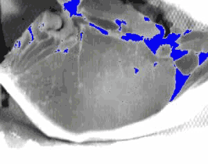
Figure 5: Fatty areas minus the subcutaneous fat region
The resulting worksheet is shown in figure 6. The first three and second three columns are the measurements of the blue overlay regions from figures 4 and 5 respectively. A macro was then written to compute the total and percentage areas with and without the subcutaneous fat region. These results are shown in column H. As expected the percentage of fat without the subcutaneous region is dramatically reduced.

Figure 6: Measurement of fat object x,y positions and areas. Fat percentages in column H were computed with a macro.
The View, Graph feature and the x,y center of mass measurements were used to display the spatial distribution of the fat objects. This is shown in Figure 7.
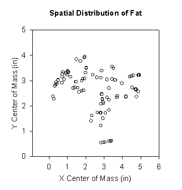
Figure 7: Spatial distribution of fat marbling